Piping on River Barrages
Prof. Dr.-Ing. Martin Achmus / M.Sc. Marx Ahlinhan
Introduction
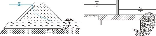
Piping is an erosion mechanism which is very relevant for river barrages as well as for dams and dikes. The under-seepage of such structures in soils sensitive to erosion (e.g. fine-grained, but non-cohesive soils like fine or medium sand) can lead to the development of a pipe, in which soil material is transported. With sufficient hydraulic gradients, the pipe development progresses from the downstream to the upstream side. At the end of this process the total failure of the barrage or dam occurs.
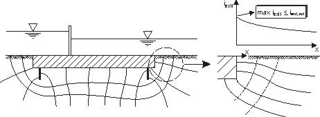
Such processes usually begin at the downstream exit of the seepage flow. Thus, besides the soil type, the hydraulic gradient at this location is decisive for a possible initiation of the piping process. With the exit gradient method, this hydraulic gradient iexit is determined by means of a flow net and is compared with an admissible hydraulic gradient dependent on the soil type. This method is schematically shown in Fig. 2.

Decisive for the use of this design method is the question, which exit gradients are critical or admissible, respectively. Theoretically, assuming a vertical upwards directed flow the critical value given in equation 1 applies. In normal cases, this value lies between 0.9 und 1.1.


Admissible values used in practice lie between 0.14 und 0.25, which implies factors of safety of 5 to 6. However, this seems justified, since the actual factor of safety is much lower due to effects of soil heterogenities and subsoil disturbances.
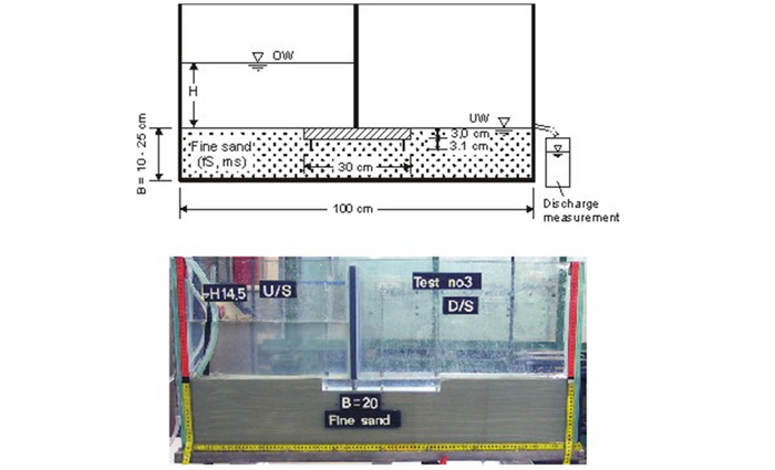
To be able to estimate the actual factor of safety, erosion tests have been carried out, in which disturbances in the subsoil at the downstream end of the barrage were simulated. The physical model is shown in Fig. 3.
The soil used was a uniform fine to medium sand. In two test series the sand was placed in the box once with an average void ratio of e = 0.92, which corresponds to a loose to medium dense state (relative density Dr = 0.40) and once with e = 0.72, corresponding to a dense state (Dr = 0.88). The thickness of the sand bed below the barrage was varied between 10 and 25 cm. Two barrage sections, one with two cut-off walls at both ends of the foundation and one without cut-offs, were investigated.
Starting from a constant water level, the level on the upstream side of the model barrage was increased stepwise. After each step the evolution of stationary seepage conditions was waited for. For this the seepage discharge and, by means of piezometers, the water pressures beneath the foundation were measured. Then the downstream soil bed was disturbed with the help of a thin needle to simulate disturbance and to create favourable conditions for the start of piping erosion. If no erosion occurred, the upstream water level was increased further.
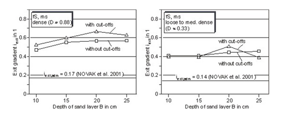
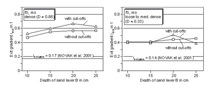
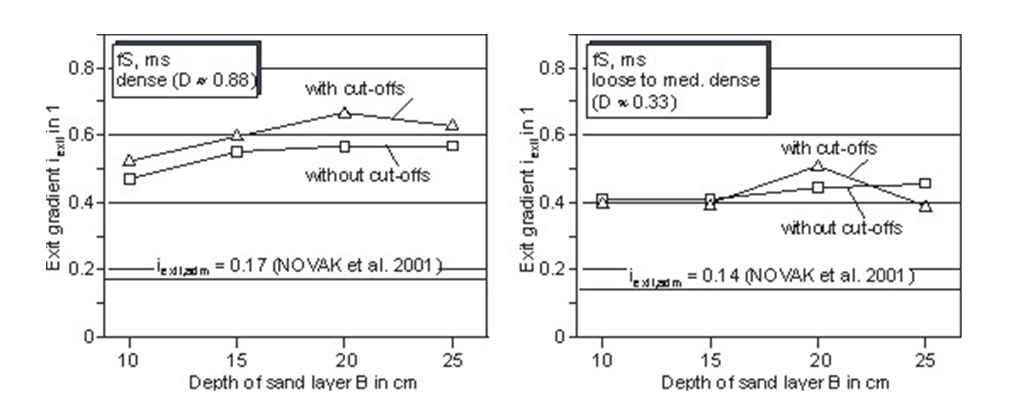
After reaching a certain water head on the upstream side, for both cases with and without vertical cut-offs a local erosion funnel evolved at the downstream end of the foundations. In this region the seepage force equaled the soil weight, so that the soil grains were moving around. Since this looks like as if the sand is boiling, the zone is called the 'boiling zone'. This state is stable, i.e. transportation of soil grains and a further progress of the piping channel only occurs when the water head is increased further. Thus, the water head differences at the start of erosion and at the failure state have to be distinguished In Fig. 4 the exit gradients determined by a back-calculation from the experimentally obtained water heads belonging to the begin of piping are shown. A slight dependence of the critical gradient on the thickness of the sand layer is found. Also for a barrage without cut-offs tendencially lower values were obtained.
However, neglecting these more or less minor effects, the following critical gradients (representing the begin of the piping process) can be given:
- Fine to medium sand, dense state: iexit,crit = ca. 0.50
- Fine to medium sand, loose to medium dense state: iexit,crit = ca. 0.40
According to these results, the admissible exit gradients used in practice imply a factor of safety of about 3.0
The model tests reported here make it clear that under extremely unfavourable conditions, i.e. very favourable conditions for piping, the erosion can begin at hydraulic gradients - calculated by means of a two-dimensional model - much lower than the theoretical value. Piping in fine sand was observed to begin at water head differences belonging to calculated exit gradients of about 0.4 for the loose to medium dense state and of about 0.5 for the dense state.
Assuming these values to be the real critical exit gradients, the admissible exit gradients proposed by Novak et al. imply a real safety factor of about 3. Higher exit gradients are necessary to induce failure of the structure, leading to safety factors of 4 and higher.
This makes evident that the process of piping is to a high degree characterized by subsoil heterogenities and disturbances, which in regular cases can not directly taken into account. On this background, the high safety level implied in the admissible gradients applied in practice seems to be justified. However, further investigations on admissible gradients are desirable and necessary.
Publications
[Translate to Englisch:] [1] Mansour, B.G.S., Achmus, M. (2003). Finite Element Analysis for old Barrages with upstream low permeability soil blanket. 10th Int. Colloquium on Structural and Geotechnical Engineering, Ain Shams University, Cairo, 22-24 April.
[2] Achmus, M., Mansour, B.G.S. (2003). Comparing finite element and empirical analysis methods for the Assiut barrage apron. Hydropower & Dams, Issue Three, 2003
[3] Mansour, B.G.S., Achmus, M. (2004). Comparison of the methods for the design of the River Nile barrages with respect to piping. Hydro 2004. Portugal
[4] Mansour, B.G.S. (2005). Investigations on Design and Rehabilitation Options for River Barrages with Special Respect to Piping. Mitteilungen des Instituts für Grundbau, Bodenmechanik und Energiewasserbau, Universität Hannover, Heft 62
[5] Achmus, M. (2006). Untersuchungen zum Nachweis gegen Erosionsgrundbruch an Stauwerken. 2. Symposium "Sicherung von Dämmen, Deichen und Stauanlagen",Universität Siegen, Februar 2006
[6] Achmus, M., Mansour, B.G.S. (2006). Considerations and Model tests on the Design of River Barrages with Respect to Piping. 3rd Int. Conference on Scour and Erosion, Amsterdam, 1-3 Nov. 2006.