Offshore-Foundation-Drilling®
Supervisor: Prof. Dr.-Ing. Martin Achmus
Researcher: Dipl-Ing. M. Narten
Duration: 2011-2013
Funded by: Herrenknecht AG und der Hochtief Solutions AG.
In offshore foundation engineering different foundation elements may be applied. If monopiles are used they have to be installed usually by impact driving. The applicability of monopiles is restricted by the technical practicability and the geology of the location. Also because of the driving work during installation and the local spread of offshore wind parks higher impacts by acoustic noise to marine life is to be expected.
HOCHTIEF AG and HERRENKNECHT AG worked together to solve this problem and developed a technical solution, the Offshore Foundation Drilling® (OFD®).
Offshore Foundation Drilling® as an alternative manufacturing method of conventional pile foundation is investigated in detail. While using the vertical drilling technique for monopile foundation an annular gap of about 5 cm will occur. This is due to an overlap at the pile base in relation to the outer pile diameter and is required to reduce skin friction during the propulsion. Directly above the pile widening at the pile base the annular gap during propulsion is continuously supported by grout. The grout performs a bond between soil and pile because of subsequent curing. To prevent potential water infiltration the steel pipe leads the drill bit by a defined amount and the water level inside the pipe is maintained above the level of outer water level.
In laboratory and full-scale field tests the soil-pile system is investigated.
Here the question about the frictional connection between soil and pile respectively the bedding of the pile was of main interest. Furthermore the loadbearing effect of the grout material in combination with potentially loosened soil area due to the drilling process and the soil closed-by was considered. Also, the influence of loosening should also be quantified in small-scale tests
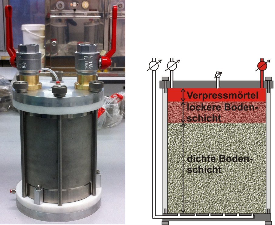
To analyse the general behavior of the pile-grout-soil-system, laboratory tests are carried out at IGtH firstly. In this case different varied systems have been studied in a closed pressure device. At first the soil with defined relative density was inserted at the bottom with a height of 20 cm in a pressure cell (diameter about 20 cm, height about 25 cm) divided into a loose and a dense area. Thereupon the grout was injected in the upper sector (ca. 5 cm) of the closed cell under a defined pressure (up to 6 bar) (picture and schematic diagram in Figure 1).
In laboratory tests the following parameters were varied: pressure, loose area, curing time, soil material and grout material.
After a certain hardening of the grout material a load-displacement-curve was recorded for each sample as well as the visual penetration of the grout was determined.
The tests are used to discover the effects of the different circumstances respectively boundary conditions of the experiment. However, a qualitative tendency of the particular influence was concluded .
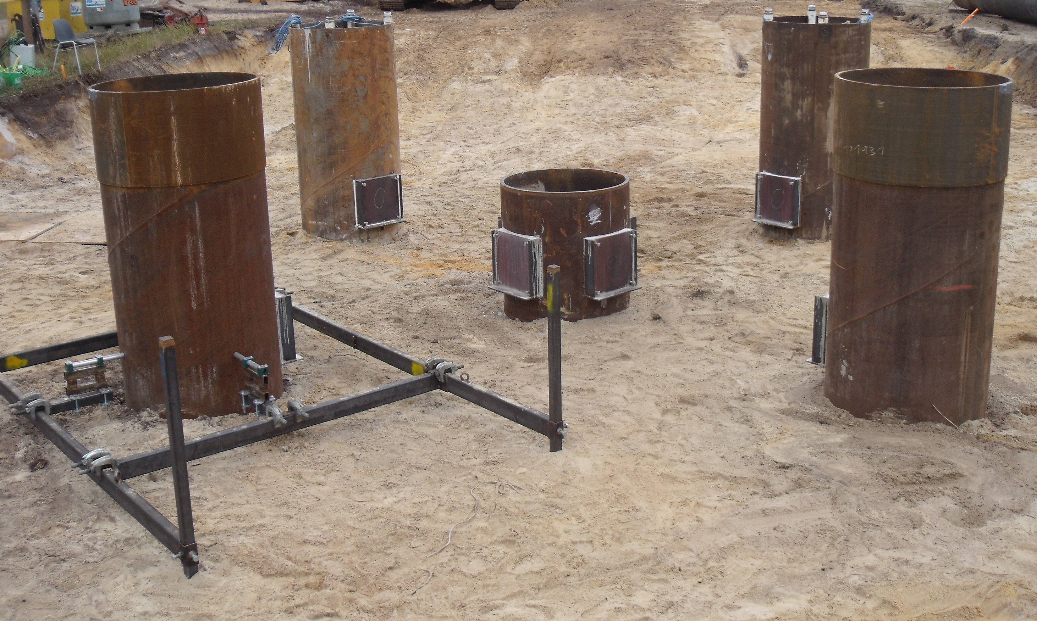
In cooperation with the HERRENKNECHT AG and based on the results of the laboratory tests the parameters for the scaled field tests were determined and scaled tests with the OFD®-method and conventional driving process were arranged (Figure 2). Additionally a finite-element-model was created to transfer the results of the field test on a scaled pile with real dimensions. Thereby the boundary conditions of the field test as well as the size effect was considered.